

Works Summary:
- Decommission 6no. Danfoss FLX15 Pro inverters.
- Remove 6no. Danfoss FLX15 Pro inverters, keep working ones on site as ‘spares’. Remove and recycle failed units.
- Remove 6no. AC supply cables from AC supply pillar.
- Modify inverter support framework to take new inverter & DC Isolator enclosure.
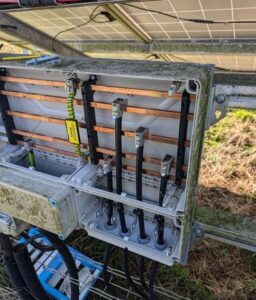
- Fit 1no. new STP110-60 (CORE2) inverter, and 1no. new IMO DC Isolator enclosure.
- Modify Hensel AC supply pillar with new Hensel parts and busbar fuses.
- Fit 1no. new AC supply cable between Hensel AC supply pillar and 1no. new STP110-60 (CORE2) inverter.
- Re-run 18no. DC strings into 9no. IMO DC Isolators in 1no. new IMO DC Isolator enclosure, and then on to inverter.
- Test all strings.
- Run ethernet cable from 1no. new STP110-60 (CORE2) inverter to Meteocontrol datalogger.
Issue: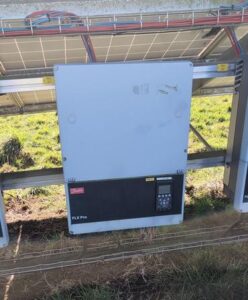
Client has 576kWp solar PV system consisting of 32no. Danfoss FLX15 Pro inverters installed in 2012.
All inverters are out of warranty. Many inverters have failed over the years. Danfoss ceased making these inverters in around 2014, and SMA purchased the Danfoss stock and continued offering technical and service support for a few years until they also ceased support in around 2019.
We sent several failed Danfoss FLX15 Pro inverters for repair but mostly found they were irreparable due to failed main circuit boards.
Solution:
We replaced a bank of 6no. working Danfoss FLX15 Pro inverters with 1no. new STP110-60 (CORE2) inverter. The idea being this would free up ‘working Danfoss inverters’ to be used as ‘spares’ for when we need to replace other Danfoss FLX15 Pro inverters as they fail. Until such a time when the spare Danfoss run out, and then we will need to look at repeating again by replacing another bank of 6no. working Danfoss FLX15 Pro inverters with 1no. new STP110-60 (CORE2) inverter.
Challenges:
The old existing Danfoss FLX15 Pro inverters were daisy chained back to the Meteocontrol datalogger in RS485 data cable. The new STP110-60 (CORE2) inverter used Ethernet TCP/IP data protocol, so we had to run a separate ethernet comms cable temporarily overground to the Meteocontrol datalogger and configure this to enable data flow for remote monitoring. We also needed to update the system configuration on the Meteocontrol VCOM portal. The client will subsequently dig a new trench and we will return to site to re-run Ethernet cable in a new underground duct.